
Use Claude to Make Controlled Changes in STAAD.Pro
A modeling change can take only a moment—and still leave you checking coordinates, loads, and supports afterward. With an OpenSTAAD MCP connection, you can describe a supported task in plain language and have Claude interact with STAAD.Pro. That can help with basic frame geometry, member properties, supports, loads, and targeted revisions.
The useful part isn’t handing over engineering judgment. It’s making routine model edits through a clear request, then reviewing the result in your own model. This walkthrough shows how to set up the connection, create a simple portal frame, change its ridge height, and build verification into your workflow.

Connect Claude to STAAD.Pro with OpenSTAAD MCP
The connection uses Model Context Protocol (MCP), which lets Claude work with external tools through a configured server. For this workflow, the bridge is the OpenSTAAD MCP extension, distributed as an .mcpb package.
Once installed and enabled in Claude Desktop, the extension lets Claude issue supported actions to STAAD.Pro. Without that connection, Claude can explain how to build a frame. With it configured, Claude can carry out supported modeling operations in the open application.
Start in a blank or disposable model while you learn the workflow. Before using the connection on project work, save a separate copy. That gives you room to inspect changes without putting your working model at risk.

Set Up the OpenSTAAD MCP Extension
Follow the extension’s installation requirements and check the release information for the version that suits your setup.
- Find the OpenSTAAD MCP GitHub releases page. Download the appropriate
OpenSTAAD-MCP.mcpbpackage. Version 1.2 was used in the demonstrated workflow; check the release page for the version appropriate to your installation. - Open Claude Desktop settings. Go to the extensions area and find the option to install an extension. Menu labels may vary by version.
- Select the downloaded
.mcpbfile. Preview and install the extension. - Review directory permissions. Give access only to the folders needed for your modeling work, rather than an entire drive.
- Enable the extension. Confirm its requirements are met and complete any configuration steps.
- Open STAAD.Pro with a test model. Start with a blank model so you can inspect the first changes easily.
A dedicated test or project folder is a better starting point than broad access to unrelated files. Keep the scope of access as narrow as your workflow allows.

Create a Portal Frame with a Specific Prompt
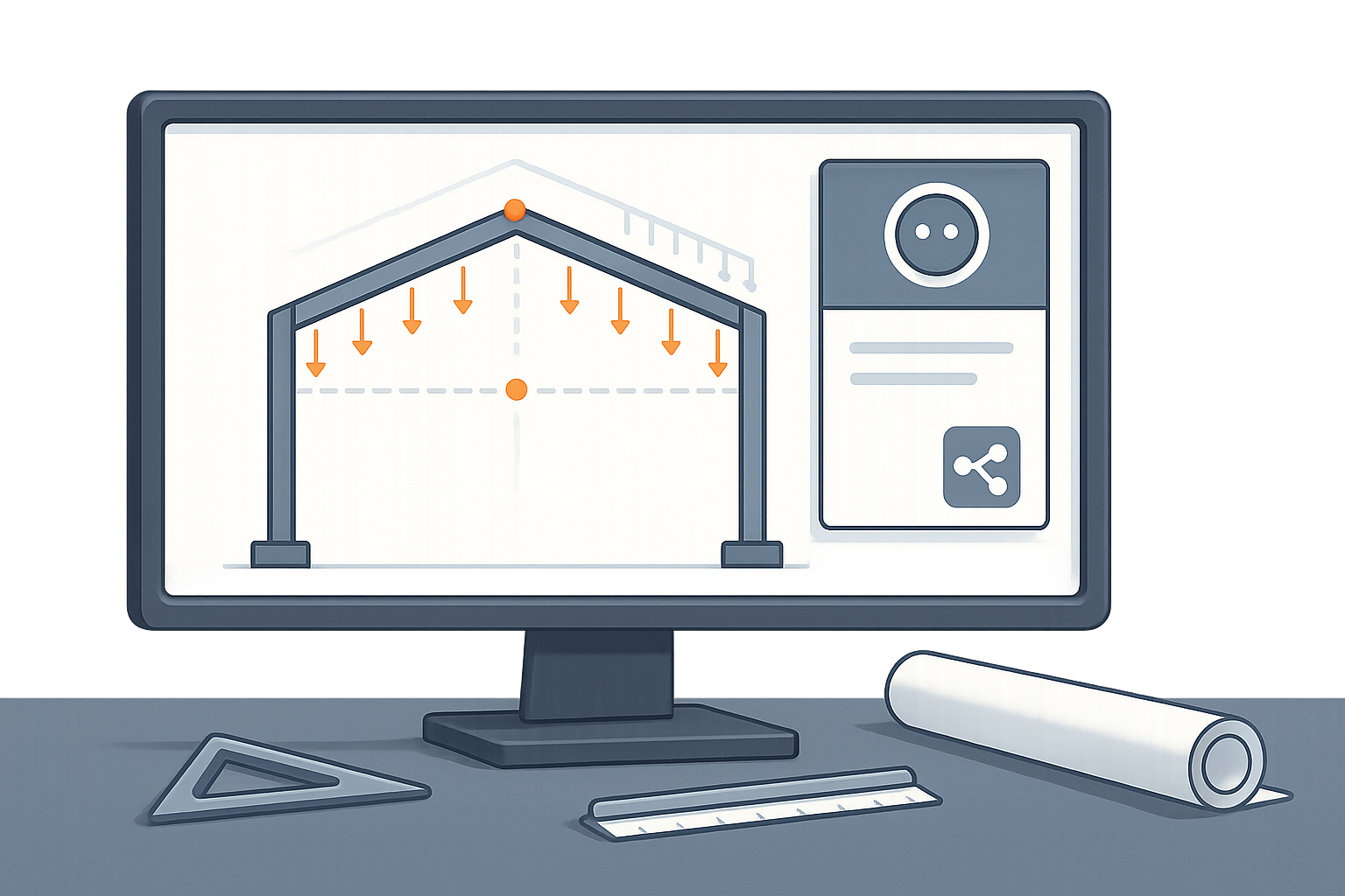
A 2D steel portal frame makes a useful first exercise. It’s small enough to inspect carefully but includes several common modeling operations.
The demonstrated example used:
- Span: 9 m
- Eaves height: 3 m
- Initial ridge height: 5 m
- Supports: Fixed at both column bases
- Member properties: A steel I-section
- Loading: Self-weight and a uniformly distributed dead load of 5 kN/m on the rafters
The initial request left out the span. Claude asked for the distance between the columns, and the response supplied 9 m. That’s a useful clarification—but don’t assume Claude will catch every missing engineering input.
You can make your request more controlled by specifying the geometry, units, load direction, and what Claude should do if information is missing:
In the open blank STAAD.Pro model, create a symmetric 2D portal frame with a 9 m span, 3 m eaves height, and 5 m ridge height. Use metres and kilonewtons, with Y as the vertical axis. Assign fixed supports at both column bases. Include member self-weight and a uniformly distributed dead load of 5 kN/m on both rafters, acting vertically downward in the global Y direction. Before creating the model, ask me to confirm the steel section and any other required information that is missing. Do not run analysis or make design adequacy claims. After completing the task, summarize the geometry, properties, supports, and loads assigned.
This prompt leaves section selection under your control and asks Claude to flag missing information before making the model.

Inspect the Model Before You Move On
A completed tool action doesn’t prove the model is correct. Check the result directly in STAAD.Pro before using it for further work.
In the demonstrated example, inspection confirmed:
- The eaves elevation was 3 m.
- The ridge node had a Y-coordinate of 5 m.
- The assigned section was ISMB 300.
- A dead load case contained self-weight and a 5 kN/m rafter load.
The section assignment is worth noting. The request allowed any steel I-section, so Claude selected ISMB 300. That was a modeling choice, not a demonstrated design result. The exercise did not establish that the section met strength, stability, serviceability, or applicable design-code requirements.
Use this review checklist:
- Geometry and connectivity: Check node coordinates, member incidence, and any unintended duplicate or disconnected elements.
- Properties: Confirm the section designation, material, and assignment to the intended members.
- Supports: Check their locations and restraint conditions.
- Loads: Confirm magnitude, direction, units, load case, and selected members.
For inclined rafters, distinguish a vertically acting load from one acting in a member’s local direction. Also confirm whether the specified intensity is per metre of member length or uses another load representation. A quick visual check is helpful, but it doesn’t replace checking the model data.
Change the Ridge Height Without Rebuilding
The next demonstrated task was a targeted revision: reducing the ridge height from 5 m to 4 m. Claude updated the model, and inspection of the ridge node showed a Y-coordinate of 4 m.
For revisions, say what should change and what should stay put. For example:
Modify only the ridge elevation in the current portal frame, changing it from 5 m to 4 m. Keep the span at 9 m and both eaves elevations at 3 m. Preserve the existing member connectivity, section assignments, supports, and load definitions. Ask before making any additional changes. When finished, report the changed node coordinates and summarize what was preserved.
After the edit, check the node coordinates and connected members. And don’t assume preserved load definitions mean nothing else needs review: changing rafter geometry changes member lengths and may affect total applied loading, depending on how the loads are defined.

Make Verification Part of Every STAAD.Pro Edit
A reliable workflow follows four steps: specify, execute, inspect, and confirm.
- Use explicit units and directions.
- Name the elements or properties you want changed.
- Keep each request narrow enough to review.
- Save a copy before significant edits.
- Inspect the model itself instead of relying only on Claude’s summary.
This example demonstrates basic model creation and a geometry update. It does not establish analysis accuracy, code compliance, or measured time savings. The practical benefit is direct interaction: you can describe a supported STAAD.Pro task in ordinary language while keeping responsibility for engineering decisions and the final model.
Takeaway: Use Claude to make clearly scoped STAAD.Pro edits, then verify every change in your model. Build practical AI skills for your work on Tixu.ai, a beginner-friendly AI learning platform.

Leave a Reply